 Yet Another Process (YAP) Control Algorithm
Yet Another Process (YAP) Control Algorithm
Yet Another Process (YAP) Control Algorithm
Originally Posted: 10/01/2010
Last Updated: 10/11/2010
Curt Timmerman
Big Lake, Alaska
At present, YAP has not been tested or implemented
I modified a SmokinTex electric smoker using a PID temperature control. While the PID controller maintained a more constant temperature I thought I could do better.
The PID controllers are generic and even though they can be tuned, the tuning process is very much trial and error. Also, there should be a better way to give the controller 'hints' about your process to allow it to perform better.
My initial guidelines for developing the YAP control system were:
Given a target temperature (set point) a process needs to maintain
1. At a temperature below the set point (-5% to -10%) the duty cycle will always be set to 100%
2. At a temperature above the set point (+5% to +10%) the duty cycle will always be set to 0%
3. The temperature range between the 1 and 2 is the
only area the control algorithm adjustment logic needs to act on.
Basic YAP Algorithm
|
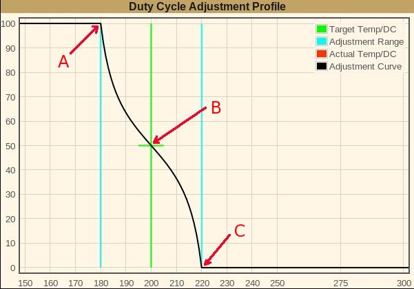
Duty Cycle Adjustment Profile The graph at the left shows a control profile for my smoker. The vertical scale represents the duty cycle from 0-100%. The horizontal scale is the temperature reading. 200F (B) is the set point with a control range from 180F (A) to 220F (C) The initial heater element duty cycle (a guess) is 50% (B). Throughout the iteration process the set point (oven temperature) remains constant and the estimated duty cycle is adjusted until a stable temperature reading is within acceptable limits of the set point. The black line represents the temperature reading vs the heating element duty cycle settings. As the temperature reading rises to 180F (A) the duty cycle remains at 100%. When the temperature rises above 180F the heater element duty cycle will be changed continuously for temperature readings indicated by the black curve line. Should the temperature rise above 220F (C), the duty cycle will be set to 0% (powered off) until the temperature again drops below 220F. This will continue until the temperature readings stablize, somewhere between 180F and 220F. If the 50% duty cycle was a good guess the temperature will stablize at 200F (B). The next section details what happens when the temperature readings stablize at a temperature other than the set point. |
|
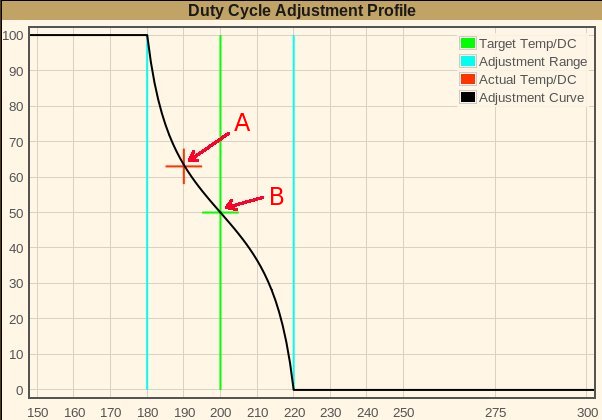
Stable Temperature Adjustment If the temperature readings stablizes at a temperature of, for example, 190F (A) the heater element duty cycle needs to be adjusted to reach the desired set point of 200F. The estimated duty cycle (B) is set to the heater element duty cycle indicated by (A), 63%, and the adjustment profile is regenerated. The new profile is shown in the next section. |
|
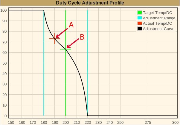
New Adjustment Profile The regenerated curve for the new estimated duty cycle of 63% (B) yields a new heating element duty cycle of 73% (A) for a temperature of 190F. The heating element duty cycle is adjusted accordingly and the next stable temperature reading will trigger a new adjustment. This is a conservative adjustment and most likely can be improved on. This stabilize/adjust process is repeated until the temperature readings stabilizes at the set point. |
YAP Mathmatics
|
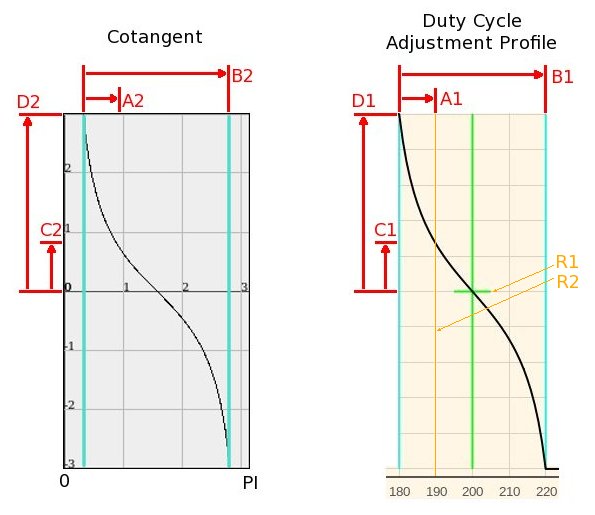
Calculating the heating element duty cycle
Based on the following settings:
A2 to B2 is the same ratio as A1 to B1: C2 = COT(A2)
C1 to D1 is the same ratio as C2 to D2:
The heater element duty cycle is: The next section shows how B2 is derived |
|
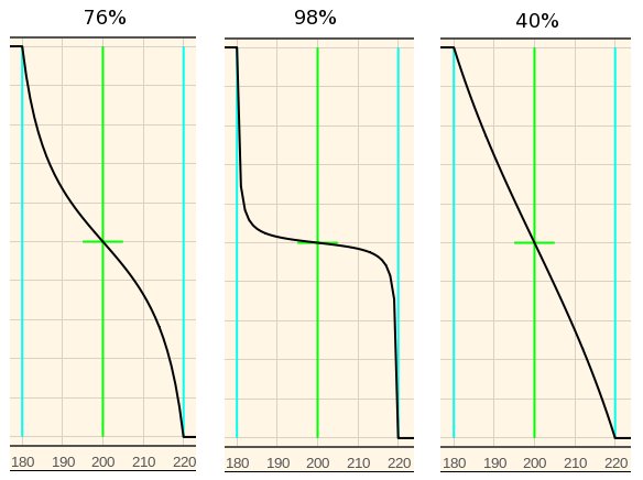
Determining the shape of the duty cycle adjustment curve The behaviour of the adjustment curve is modified by selecting different per centages (1-99) of the cotangent cycle. This per cent becomes a factor of PI centered on PI/2. The 76% curve is what was used in the examples above. This is the value I am using to test my implementation. The 98% curve has very steep gradients. This would require a very precise output control system. 50% and below become essentially a straight line and would be better suited to a simple linier equation. The main factor limiting how high you can set this percentage is the precision of the control system. If set too high a dead space will be created around the set point. This is where the temperature reading is above/below the set point but the indicated duty cycle is the same as the current duty cycle. |
What is a Stable Temperature?
|
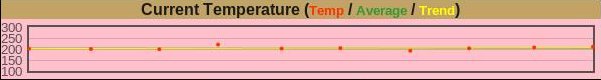
Current Temperature Reading One of the things I observed on my PID controller is the variance of the temperature readings. The readings bounced around with a 4-5 degree swing. I expect to take an average of the last 10 readings and use this as the current reading. |
|
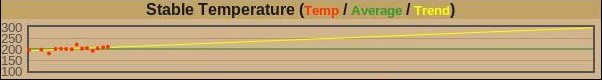
Stable Temperature Determination This may be the most difficult calculation of the algorithm. Initially, I will base it on a sample of the latest 100 readings. The stability will be determined by the calculated slope and the average will be used for the actual temperature reading. |
Improvements, Enhancements, and Adjustments

|
Adjustment curve and range In many systems the positive and negative control are not symetrical. To compensate for this different control curves could be generated for adjustment above and below the set point. The control range above and below the set point don't necessarily have to be the same value. Zero / 100% Duty Cycles Conditions may reuire that a zero duty cycle may not be completely off or that 100% may not actually imply full power.
Embedded systems
|
Current Testing
|
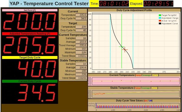
Test Application
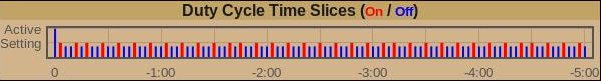
The heading line displays the current time and elapsed time. |
|
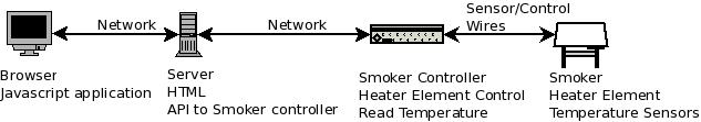
Control Testing Set Up
|
|
Duty Cycle
|
Future Directions`
|
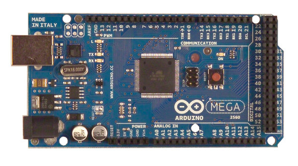
Arduino Mega 2650 My goal here is to build a completely self-contained smoker controller. |
Resources